
Most service truck specifications get built backward. The body goes on the chassis, the compartments get laid out, and somewhere near the end of the process someone asks where the power system is going and how much air it needs to make. By then, the decisions that matter have already been made.
For contractors spec’ing a construction service truck around a diesel all-in-one power system, the choice between the 40 and 60 CFM configurations belongs at the front of that conversation. Not because the two units differ much physically, but because the air rating drives a series of downstream decisions about body layout, exhaust routing and control access that get expensive to revisit after the build is underway.
Here is what to work through, and in what order.
START WITH SUSTAINED AIR, NOT PEAK AIR
Both configurations deliver 150 PSI with maximum pressure up to 175 PSI. The difference is volume: 40 CFM versus 60 CFM. The temptation is to size by the largest tool in the inventory, which almost always produces the wrong answer.
There is a second reason is oversizing backfires. The compressor and the welder draw from the same 24.8 horsepower engine, so air capacity you specify but rarely use is engine output permanently allocated away from the arc. Sizing air to the work is not only a cost decision. It is a power allocation decision.
Air tools are rated at consumption under continuous operation, but few tools in construction service work run continuously. An impact wrench cycles. A hammer drill runs in bursts. What matters is the sustained draw of the tools your crew runs together, plus whatever headroom the work demands.
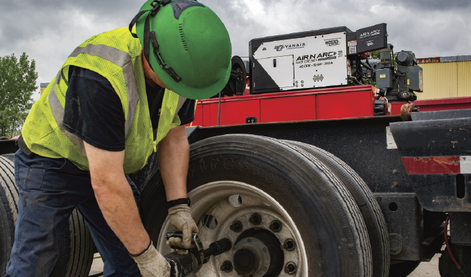
The 40 CFM configuration handles most of the single-technician service work: impact wrenches for wheel and track service, air ratchets, blow guns, tire inflation and light chipping. It is also the stronger choice for carbon arc gouging, which is where the power allocation point becomes concrete. A quarter-inch carbon typically consumes only 20 to 30 CFM, since the air is doing nothing more than clearing molten metal as the arc removes the weld. Specifying 40 CFM covers that demand while leaving more engine output available to the welding arc, which is the part of the operation doing the work. For contractors whose service trucks see regular gouging on structural repair, that trade favors the smaller compressor.
The 60 CFM configuration earns its place in three situations. The first is genuinely high-consumption tools. Air-powered sandblasters and grease pumps draw volumes that will starve a 40 CFM system into duty-cycle limitations. The second is multiple simultaneous users. Two technicians pulling air at once effectively halves what either one sees, and a two-person crew on a large machine teardown will find 40 CFM confining. The third is the long airline. Every foot of hose between the compressor and the tool costs pressure, and on a jobsite where the truck cannot park next to the equipment, extra volume at the source compensates for what the run gives away.
What about operations that need both? The unit runs without an air vessel but adding an air tank changes what the option is for. Rather than a requirement, the tank becomes a productivity tool, banking stored air for short bursts of high demand. That gives a 40 CFM machine optimized power delivery for gouging and routine service, with reserve capacity available when a job briefly calls for more.
Both configurations use the same Vanair rotary screw compressor with electronic inlet control for precise pressure regulation, and both are assembled in the USA.
DO THE WEIGHT AND SPACE MATH
The unit carries a 47.5 by 21.4 by 25.6-inch footprint, extending to 48.2 by 21.9 by 27 inches with fittings, at 750 pounds dry.
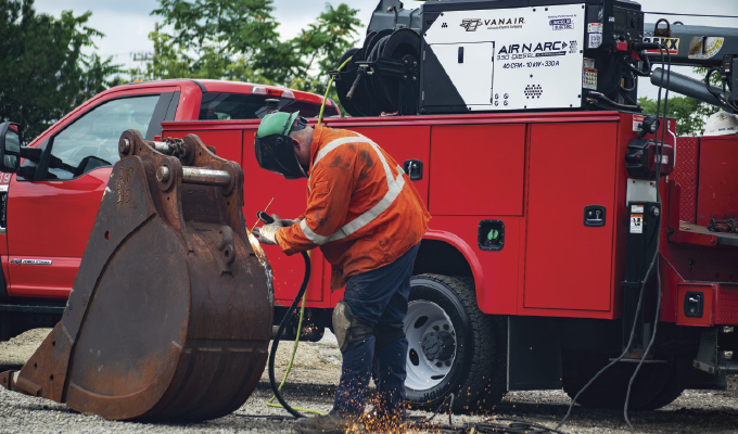
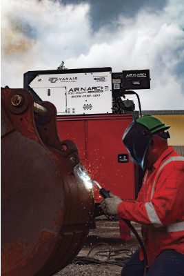
That number is worth comparing to what it replaces. A truck carrying a separate engine-driven welder, a standalone compressor and a portable generator, is carrying three engines, three fuel considerations and three sets of mounting hardware. Vanair’s Air N Arc 330 Diesel all-in-one power system consolidates all of it, plus battery boost and charge into one enclosure driven by a single 24.8hp, three-cylinder, water-cooled Kubota diesel.
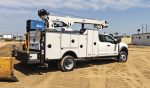
The footprint is compact enough to mount on top of a side pack rather than consuming bed floor, which is the configuration most contractors end up choosing. That decision returns the bed to cargo, material and larger tooling. On a construction service truck where bed space is perpetually short, this is often the single biggest practical gain from consolidation.
The unit ships with a two-point lift bail. Mounting a 750lb assembly onto a side pack is a rigging operation, and a designed lifting point makes it a routine one.
EXHAUST ROUTING IS A BODY DECISION, NOT A MACHINE DECISION
Air N Arc 330 Diesel is ordered with either top or rear exhaust discharge. This is specified at the time of order, which means the body layout has to be settled first. The determining factor is what sits adjacent to the unit and where crews stand. A top-mounted unit on a side pack with a crane boom or ladder rack overhead may need rear discharge to keep heat away from equipment above it. A unit mounted where the rear discharge would vent toward a work area or a compartment door needs top discharge instead. Enclosed or partially enclosed installations change the calculation again. Importantly, walk the finished body layout before placing the order. Reversing this decision after delivery is not a field modification.
PUT THE CONTROL PANEL WHERE WORK HAPPENS
The remote-mounted control panel can mount directly to the end of the machine or, more commonly, remote into a side compartment on the body. The safety argument for remote mounting is straightforward and worth making to whoever signs off on the build. When the panel lives on the machine and the machine lives on a side pack, every function change means climbing into and out of the bed. On a construction site, in weather, with tools in hand, that is a fall exposure repeated dozens of times a day. Moving the panel to a compartment at standing height eliminates it.
The panel itself carries an electronic high-visibility LCD display with button controls, a selector knob for menu navigation and mode selection, and a key switch. It also carries power outlets: dual 120-volt GFCI receptacles and a single 240V, 50-amp receptacle. That last detail affects placement more than the display does. The panel location determines where crews plug in, so it should sit near where they work rather than wherever there happens to be an empty compartment. A wireless remote-control kit is available as an option for applications where even compartment access is inconvenient.
Also worth flagging early: the unit includes a 240V receptacle for the Vanair EPEQ level 2 EV charger. For contractors with electric equipment on site or anticipating it, this is existing capability rather than a future retrofit, and it may influence where the panel goes.
THE WELDING AND POWER CAPABILITY IS FIXED, SO SPEC AROUND IT
Both configurations carry identical welding and electrical output, which simplifies this part of the specification. The welder is a Lincoln Electric DC multi-process unit with Lincoln Electric chopper technology, delivering constant current for stick, gouging and TIG at 35 to 330 amps, and constant voltage for MIG and flux-cored arc welding at 14 to 40V. Chopper technology was developed to give engine-driven welders the arc control associated with inverter machines, which matters for construction work involving both structural repair and thinner-gauge fabrication.
The generator is a Lincoln Electric AC unit producing 10kW of continuous single-phase output at 120/240V, direct-coupled rather than belt-driven and engineered for smooth output with minimal distortion. Battery boost runs 330A at 12/24V with 50A of 12/24V charge, and the unit offers charge back to chassis mode at up to 50A. That last function routes charge from the Air N Arc back into the truck’s own starting batteries while the unit runs, so a chassis that sits all day with the engine off, powering lights, telematics and accessories, does not send the crew looking for a jump at quitting time.
What the body build needs to accommodate is the accessory list rather than the base capability. If the operation runs MIG in the field, the Lincoln LN25X suitcase feeder needs a home and a route for cable. TIG work means a torch and a gas bottle, and a bottle needs secure mounting that most standard bodies do not include. Welding cables in 25- and 50-foot lengths, cable extensions, rod storage and a helmet all need compartment space allocated during design rather than found afterward.
FUEL, COLD WEATHER AND SERVICE ACCESS
The Air N Arc 330 Diesel uses an integrated fuel system built into the chassis, drawing from the truck’s tank rather than requiring a dedicated supply. This eliminates a separate tank, that tank’s mounting and the weight and space both consume. The integrated fuel system also removes a second fuel fill point from the daily routine. A remote fuel tank is available as an option where chassis integration is not practical.
For cold-climate operations, the unit comes with an integrated 12VAC cold weather package, with a 120VAC engine block heater available as an option. A brushless electric cooling fan handles thermal management year-round.
On serviceability, the unit uses latched, lift-off access panels reaching the mechanical functions, with side panels opening to all major service points. The shrouding is powder-coated galvannealed steel. During body design, verify that the panels can open in their mounted position. A unit installed tight against a headache rack, or a crane pedestal can become difficult to service in ways that are obvious on the truck and invisible on the drawing.
THE SEQUENCE THAT WORKS
Determine sustained air demand from the tools your crew runs together and select 40 or 60 CFM from that. Lay out the body and confirm mounting position. Specify exhaust discharge from that layout. Place the control panel where the crew works, not where space is left over. Allocate compartment space for welding accessories and gas bottles. Confirm service panel clearance.
Handled in that order, the specification produces a truck built around the work. Handled in the order many builds follow, it produces a truck the crew works around.
for more information
To learn more, visit www.vanair.com/air-n-arc-330-diesel-all-in-one-power-system/.